Medium-rigidity CNC lathes and machining centres occupy a dominant position in general machining workshops. Compared with heavy-duty high-rigidity machine tools, they offer competitive investment costs and sufficient flexibility for mixed batch production.
However, one common puzzle troubles countless machinists:
Many operators mistakenly attribute premature insert failure to poor insert quality, while ignoring the fundamental constraint: the limited dynamic stiffness of the machine-process.
Case Details
This article breaks down typical failure modes, root causes and actionable optimisation strategies, supported by real workshop cases collected by field engineers from
Zhuzhou Century Tool.1. Core Characteristic of Medium-Rigidity Machine Tools
Medium-rigidity CNC equipment has acceptable static stiffness under light cuts, but exhibits obvious elastic deflection and vibration risks under moderate-to-heavy cutting loads.
The whole process system forms a vibration loop consisting of four parts:
Machine structure + spindle + tool holder + workpiece fixture
Once cutting excitation frequency approaches the natural frequency of the system,
chatter vibration (self-excited vibration) occurs.
High-rigidity machines can suppress amplitude deflection; medium-rigidity equipment cannot absorb periodic cutting shocks effectively, transferring cyclic impact stress directly to the carbide cutting edge.
2. Main Failure Mechanisms of Indexable Inserts (With Workshop Cases)
2.1 Cutting Edge Chipping & Micro-fracture (Most Common Failure)
Vibration generates repeated impact load on the cutting edge. Continuous tiny shock creates micro-cracks inside carbide substrate; cracks expand rapidly under cyclic load and eventually cause edge chipping. Interrupted cutting, shoulder transition, plunge-in and plunge-out amplify vibration peaks. Even standard recommended parameters will trigger insert fracture on medium-rigidity machines.
Field Case 1 – Turning 45# carbon steel shaft parts
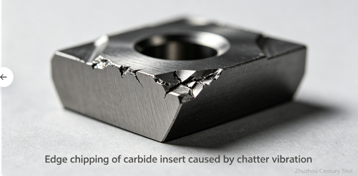
A job shop used medium-rigidity CNC lathes to machine medium-carbon steel shafts. Operators copied parameters validated on heavy rigid lathes: Vc=180 m/min, ap=1.2 mm, f=0.18 mm/rev. Sharp positive-rake coated inserts suffered random edge chipping after processing only 8–12 workpieces.
The workshop initially suspected defective inserts and switched to three different brands, but failure remained consistent.
After receiving the customer’s enquiry, technical engineers from
Zhuzhou Century Tool visited the site and detected obvious chatter noise during shoulder transition.
Optimisation measures: Reduce depth of cut to 0.6 mm per pass; adjust spindle speed to avoid resonance zones; select tougher inserts with edge honing. After adjustment, average insert service life rose to over 45 pieces without random breakage.
Symptom: Uneven, jagged damage along cutting edge, random breakage without obvious gradual wear.
2.2 Accelerated Flank Wear & Notch Wear
Vibration makes the insert repeatedly separate and re-contact the workpiece surface. The intermittent rubbing action accelerates abrasive wear at depth-of-cut line, forming obvious notches. Work-hardened layers on ferrous alloys further aggravate notch wear, gradually weakening edge strength and triggering subsequent breakage.
Field Case 2 – Milling 304 stainless steel base plates
A machinery factory used medium-rigidity vertical machining centres to mill stainless steel thin plates. Inserts displayed severe notch wear at the depth-of-cut line, failing within short cycles.
Workpiece thin-wall structure reduced overall system rigidity, and unstable vibration caused cyclic friction at the cut boundary.
Our specialists proposed targeted improvements: Add auxiliary support fixtures for thin plates; adopt arc-in tool paths instead of vertical plunge; increase feed moderately to avoid edge rubbing. Notch wear was greatly suppressed after modification.
2.3 Built-Up Edge (BUE) & Adhesive Failure
Chatter leads to unstable chip formation. Discontinuous chip flow increases friction temperature fluctuation. For ductile materials (stainless steel, low carbon steel, brass), workpiece material easily welds onto the rake face. When BUE periodically peels off, it tears small fragments from the carbide edge, shortening insert life and destroying surface finish simultaneously.
Field Case 3 – Turning brass fittings for hydraulic systems
A customer machining brass components on medium-rigidity lathes frequently encountered built-up edge. Fragments of brass peeled away together with carbide particles, creating rough surface and unpredictable tool life.
Vibration caused unstable chip curling. Following recommendations from
Zhuzhou Century Tool, the workshop switched to neutral-rake inserts with anti-adhesion coating, together with optimised coolant targeting the cutting zone. BUE was effectively controlled.
2.4 Thermal Fatigue Cracking
Vibration causes unstable contact between insert and chip. The cutting zone alternates rapidly between high-temperature contact and air cooling. Repeated thermal expansion and contraction produce thermal fatigue cracks, especially for coated carbide grades used in semi-roughing and roughing operations.
3. Key Contributing Factors in Medium-Rigidity Machining Systems
3.1 Excessive tool overhang
Long tool holder overhang greatly reduces system rigidity. Even minor machine deflection turns into large amplitude vibration at the cutting tip. Many operators extend overhang for workpiece clearance without adjusting cutting data accordingly.
3.2 Unsuitable aggressive cutting parameters
Parameters optimised on high-rigidity machines cannot be copied directly. Excessive depth of cut or improper feed generates huge dynamic cutting force, exceeding the vibration suppression capacity of medium-rigidity equipment.
A typical error: too low feed rate, causing the edge to rub rather than shear material. Rubbing generates massive heat and stimulates vibration.
3.3 Weak workpiece clamping
Thin-wall shafts, thin plates and long slender workpieces increase system flexibility. The whole system becomes more susceptible to resonance when both workpiece and machine lack sufficient rigidity.
3.4 Mismatched insert grade & geometry
Sharp positive-rake inserts with thin edge honing deliver low cutting force but poor impact resistance. Under vibratory conditions, brittle sharp edges chip easily. Many users select wear-resistant hard grades, which are inherently sensitive to impact and vibration.
3.5 Poor holder maintenance & insert seating
Dirty insert pockets, worn clamping screws and loose turret components introduce extra clearance. Under vibration, inserts shift slightly during cutting and fail prematurely.
4. Practical Solutions to Extend Insert Service Life
4.1 Optimise setup to improve system rigidity
- Minimise tool overhang; use the shortest possible tool holder assembly.
- Reinforce workpiece clamping; apply tailstock support for slender shafts; use auxiliary supports for thin-wall parts.
- Regularly maintain turrets, spindles and guide rails; eliminate mechanical clearance.
- Clean insert pockets thoroughly before installation; apply correct torque to clamping screws.
4.2 Adjust cutting parameters to avoid resonance
- Reduce depth of cut to lower peak cutting force; distribute stock into more passes.
- Avoid ultra-low feed rates to prevent edge rubbing; maintain the minimum chip load required for effective shearing.
- Fine-tune spindle speed to skip resonance frequency ranges; observe surface texture and noise to identify stable speed windows.
- Adopt smooth ramp-in / arc-in tool paths instead of straight plunge cuts to reduce instantaneous impact.
4.3 Select suitable carbide inserts for unstable machining conditions
- Grade selection: Choose tougher substrate grades with higher cobalt content instead of ultra-wear-resistant brittle grades. For vibration-prone applications, prioritise impact resistance over pure abrasion resistance.
- Edge preparation: Select inserts with proper edge honing (T-land / hone radius) to strengthen cutting edges against chipping.
- Geometry preference: Slightly negative or neutral rake geometries improve edge stability under vibration; avoid ultra-sharp positive rake inserts for roughing.
- Coating choice: Use stable, anti-adhesion coatings (TiAlN, AlCrN) to suppress built-up edge.
4.4 Optimise cooling and chip control
Deliver sufficient targeted coolant to the cutting zone to stabilise temperature and reduce thermal fatigue. Well-controlled continuous chips reduce chip hammering against the cutting edge.
5. Conclusion
Premature carbide insert failure on medium-rigidity CNC machines is seldom caused by defective inserts. The root cause lies in insufficient dynamic stiffness of the whole machining system.
As shown in our field cases, many workshops waste time repeatedly replacing tool brands while overlooking vibration, clamping and parameter matching. Workshop technicians need to abandon the idea of directly copying parameters proven on heavy rigid machines. Systematic optimisation including clamping setup, cutting data tuning and correct insert grade selection can effectively suppress chatter vibration, eliminate random insert breakage, stabilise tool life and lower overall production costs.
If you require application support for selecting suitable indexable inserts for medium-rigidity CNC turning & milling, contact the engineering team of
Zhuzhou Century Tool for custom recommendations according to your machine model, workpiece material and machining allowance.
 A job shop used medium-rigidity CNC lathes to machine medium-carbon steel shafts. Operators copied parameters validated on heavy rigid lathes: Vc=180 m/min, ap=1.2 mm, f=0.18 mm/rev. Sharp positive-rake coated inserts suffered random edge chipping after processing only 8–12 workpieces.
The workshop initially suspected defective inserts and switched to three different brands, but failure remained consistent.
After receiving the customer’s enquiry, technical engineers from Zhuzhou Century Tool visited the site and detected obvious chatter noise during shoulder transition.
Optimisation measures: Reduce depth of cut to 0.6 mm per pass; adjust spindle speed to avoid resonance zones; select tougher inserts with edge honing. After adjustment, average insert service life rose to over 45 pieces without random breakage.